
Luminous flux
Measure of perceived light power weighted by human eye sensitivity.

Figuper · CC BY-SA 4.0
Luminous flux, also known as luminous power, is a measure of the perceived power of light as adjusted for the varying sensitivity of the human eye to different wavelengths. It is a fundamental concept in photometry, used to quantify the useful light emitted by a source.
- SI unit
- lumen (lm)
- Definition
- 1 lm = 1 cd × 1 sr
- Related quantity
- radiant flux
- Weighting function
- luminosity function
- Standardizing bodies
- CIE and ISO
- Common application
- light bulb packaging
Lore & Background
Luminous flux differs from radiant flux, which measures total electromagnetic radiation power including infrared and ultraviolet. The luminous flux accounts for eye sensitivity by weighting power at each wavelength with the luminosity function, which represents the eye's response. Light outside the visible band does not contribute. The ratio of total luminous flux to radiant flux is called luminous efficacy.
Reader's Guide
Luminous flux is often used as an objective measure of the useful light emitted by a light source, typically reported on packaging for light bulbs. Consumers commonly compare luminous flux of different bulbs to estimate apparent light output, and a bulb with a higher ratio of luminous flux to consumed power is more efficient. Luminous flux is not used to compare brightness, as brightness is subjective and varies with distance and angular spread. Measurement of artificial light sources is typically done using an integrating sphere or a goniophotometer with a photometer or spectroradiometer. Luminous flux (lumens) measures total light output, while luminous intensity (candelas) measures beam brightness in a particular direction; changing optics can alter intensity but not flux.
Did You Know?
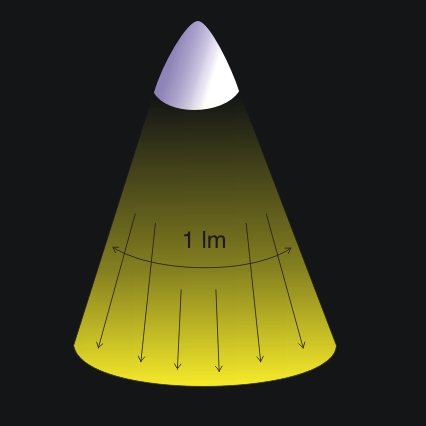
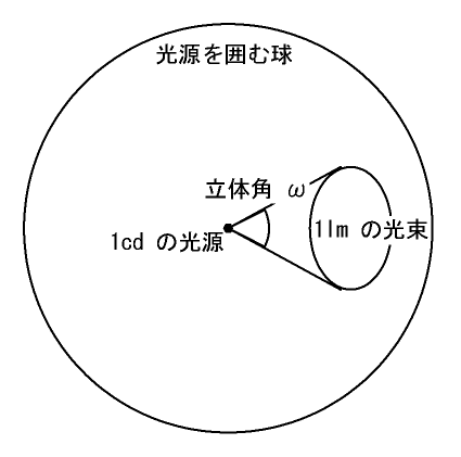
- One lumen is defined as the luminous flux produced by a source emitting one candela over one steradian.
- Luminous flux is a weighted sum of power at all wavelengths in the visible band only.
- The ratio of total luminous flux to radiant flux is called luminous efficacy.
- Luminous flux is typically measured using an integrating sphere or a goniophotometer.
Definition and Core Mechanism
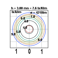
A goniophotometer is a specialized photometric instrument designed to capture how light spreads directionally from sources, fixtures, optical media, or reflective surfaces. At its heart sits a goniometer that tracks angular position using spherical coordinates, allowing the device to record the full angular distribution of transmitted, emitted, or reflected light. This capability is essential because most real-world light sources do not radiate uniformly in all directions. When the resulting data is expressed in angular coordinates, it is commonly called the luminous intensity distribution, though practitioners sometimes use the term beam pattern—a label that can also describe the light pattern projected onto a surface oriented perpendicular to the beam axis. A closely related instrument, the gonioradiometer, performs the same angular measurements but operates on a radiometric basis rather than a photometric one, meaning it is not weighted to match human visual sensitivity. This distinction matters when the goal is to characterize radiant power rather than perceived brightness.
Practical Applications and Color Characterization
The directional distribution of light carries significant weight in fields such as architectural lighting design and automotive headlamp engineering, where controlling where light goes is as important as how much is produced. A goniophotometer serves as the primary tool for quantifying this distribution. Beyond basic luminous flux and intensity measurements, the instrument can be fitted with color sensors to reveal additional characteristics of a source, including the spatial distribution of correlated color temperature and color uniformity across the beam. Another advanced application involves determining what is known as an indicatrix of diffusion or a scattering indicatrix. This is a three-dimensional surface, plotted in polar coordinates, that maps the angular distribution of relative radiant intensity, luminous intensity, radiance, or luminance produced when a medium scatters or transmits an incident beam of optical radiation. For sources that are considerably smaller than the goniophotometer itself, the instrument can still accurately capture the full luminous intensity distribution, making it versatile across a wide range of source sizes.
Structural Classifications: Types A, B, and C
The Illuminating Engineering Society mirrors this guidance in its ANSI/IES LM-75-19 standard. Type A features a fixed horizontal axis with the vertical axis mounted upon it, both oriented perpendicular to the source's main output direction. Type B inverts this arrangement, fixing the vertical axis and attaching the horizontal one, again both perpendicular to the output axis. Both A and B employ a double-column structure, making them well suited to measuring grille lamps where the lamp's symmetry axis aligns coaxially with the rotating supporter's horizontal axis. Type C, by contrast, uses a single-column layout created by removing the auxiliary column from the double-column design. It fixes a vertical axis perpendicular to the measurement line while the horizontal axis runs parallel to the source's main output direction, a configuration applied to tube lamps, spot lamps, and similar devices.
Imaging-Based Measurement and the Data Ecosystem
A newer approach to capturing luminous intensity distributions replaces the traditional rotating detector with an imaging system. In this camera-based method, a fisheye-lens camera is mounted in a port of an integrating sphere, recording the intensity data for every emission angle simultaneously. This instantaneous capture eliminates measurement uncertainty introduced by temporal effects such as source drift or temporal modulation, and it dramatically shortens the time needed to obtain a complete distribution. Because the entire angular field is acquired in a single exposure, the result is also independent of the angular resolution step chosen for the measurement. The broader ecosystem surrounding goniophotometry includes standardized data file formats like EULUMDAT, which structures luminaire radiometric data for exchange, as well as related instruments and concepts such as the goniometer, the integrating sphere, and the general discipline of goniophotometry. Together, these tools and standards form a coherent framework for characterizing how light behaves in three-dimensional space.
Gallery

Frequently Asked Questions
What exactly is Luminous flux in plain terms?
It is the photometric way of expressing how much visible light a source delivers, but filtered through how well the human eye responds at each wavelength. Instead of counting raw electromagnetic energy, it weights every wavelength by the eye's sensitivity curve so the resulting number tracks perceived brightness.
What is the SI unit and how is it defined?
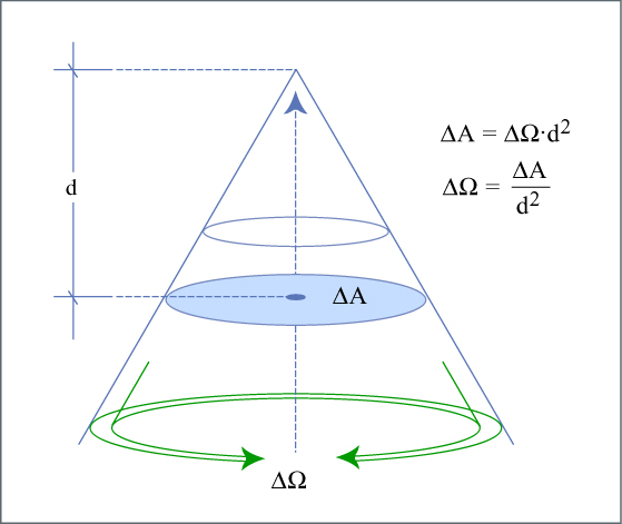
The unit is the lumen (lm), defined as one candela of luminous intensity spread over one steradian of solid angle. You will see it printed on virtually every light-bulb or LED package sold in a store.
How does Luminous flux differ from radiant flux?
Radiant flux tallies total electromagnetic power across all wavelengths with no regard to visibility, whereas luminous flux applies the CIE standard luminosity function to weight each wavelength by how visible it is to a typical human observer. Put simply, radiant flux is the raw energy; luminous flux is the portion your eyes would actually register.
Which bodies standardise the definition of Luminous flux?
The International Commission on Illumination (CIE) and ISO jointly define the luminosity function and the photometric quantities built upon it. Their specifications are what allow manufacturers worldwide to quote comparable lumen values on product labels.
More in Optics And Photonics 1-24
Elsewhere in the Optics And Photonics universe
Spotted an error? Know more?
This is a living reference — every entry is fact-audited, and reader corrections feed straight into our audit queue. Suggest an edit · See this site's audit record